
$30
Homework 2 Solution
[25 pts]
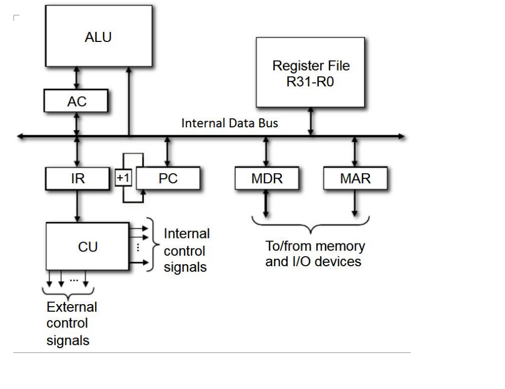
1- In order to make the pseudo-CPU more useful, suppose that we incorporate a single-port register file containing
- 8-bit registers (R0-R31). The term single-port means that only one register value can be read or written at a time. Suppose the pseudo-CPU is used to implement the AVR instruction ST -X, R14. Give the sequence of microoperations that would be required to Fetch and Execute this instruction. Note that this instruction occupies
- bits. Your solution should result in exactly 6 cycles for the fetch cycle and no more than 7 cycles for the execute cycle. You may assume only the AC and PC registers have the capability to increment/decrement themselves. Assume the MDR register is only 8 bits wide (which implies that memory is organized into consecutive addressable bytes), and AC, PC, IR, and MAR are 16-bits wide. Also, assume the Internal Data Bus is 16 bits wide and thus can handle 8-bit or 16-bit (as well as portions of 8-bit or 16-bit) transfers in one microoperation. Clearly state any other assumptions made.
[25 pts]
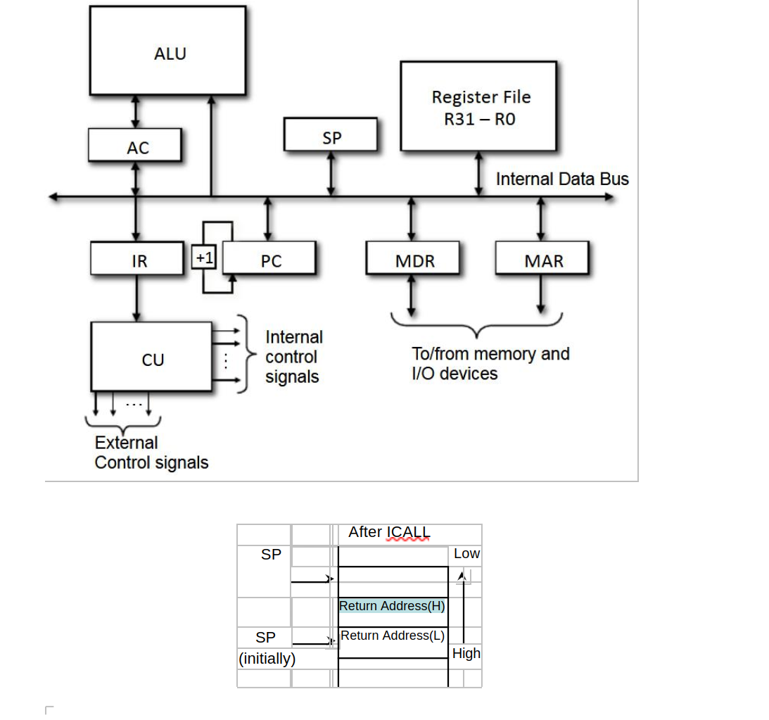
2- Now imagine that we take the pseudo-CPU (from problem 1) and add a Stack Pointer (SP). Suppose the pseudo-CPU can be used to implement the AVR instruction ICALL (Indirect Call to Subroutine) with the format shown below:
1001 0101 0000 1001
ICALL pushes the return address onto the stack and jumps to the 16-bit target address contained in the Z register. Give the sequence of microoperations required to Fetch and Execute AVR’s ICALL instruction. Your solution should result in exactly 6 cycles for the fetch cycle and no more than 8 cycles for the execute cycle. Assume the memory is organized into addressable bytes (i.e., each memory word is a byte), MDR is 8 bits, and AC, SP, PC, IR, and MAR are 16 bits. Also, assume the Internal Data Bus is 16-bits wide, and thus can handle 8-bit or 16-bit (as well as portions of 8-bit or 16-bit) transfers in one microoperation and SP has the capability to increment/decrement itself. Clearly state any other assumptions made.
[25 pts]
3- Consider the following AVR assembly code that performs 16-bit by 16-bit multiplication. Hint: See the Lab 5 documentation for relevant background information. Assume the data memory locations $0100 through $0107 initially have the values shown below. Use this information to answer the questions on page 4.
-
Data
Memory
Address
content
0100
0C
0101
00
0102
0F
0103
02
0104
00
0105
00
0106
00
0107
00
|
.include "m128def.inc" |
; |
Include definition file |
|||
|
.def |
rlo = r0 |
|
; |
Low byte of MUL result |
|
|
.def |
rhi = r1 |
|
; |
High byte of MUL result |
|
|
.def |
A = r2 |
|
|
; |
An operand |
|
.def |
B = r3 |
|
|
; |
Another operand |
|
.def |
zero = r4 |
|
; |
Zero register |
|
|
.def |
oloop = r17 |
|
; |
Outer Loop Counter |
|
|
.def |
iloop = r18 |
|
; Inner Loop Counter |
||
1. |
.org |
$0000 |
rjmp |
INIT |
|
|
|
|
|
|
|||
2. |
INIT: |
|
.org |
$0054 |
; Set zero register to zero |
|
|
clr |
zero |
||||
3. |
MAIN: |
|
ldi |
YL, low(addrB) |
; Load low byte |
|
4. |
|
|
ldi |
YH, high(addrB) |
; Load high byte |
|
5. |
|
|
ldi |
ZL, low(LAddrP) |
; Load low byte |
|
6. |
|
|
ldi |
ZH, high(LAddrP) ; Load high byte |
||
7. |
|
|
ldi |
oloop, 2 |
; Load counter |
|
8. |
MUL16_OLOOP: ldi |
XL, low(addrA) |
; Load low byte |
|||
9. |
|
|
ldi |
XH, high(addrA) |
; Load high byte |
|
10. |
|
ldi |
iloop, 2 |
; Load counter |
||
11. MUL16_ILOOP: ld |
A, X+ |
; Get byte of A operand |
||||
12. |
|
ld |
B, Y |
; Get byte of B operand |
||
13. |
|
mul |
A,B |
; Multiply A and B |
||
14. |
|
ld |
A, Z+ |
; Get a result byte from memory |
||
15. |
|
ld |
B, Z+ |
; Get the next result byte from memory |
||
16. |
|
add |
rlo, A |
; rlo ← rlo + A |
||
17. |
|
adc |
rhi, B |
; rhi ← rhi + B + carry |
||
18. |
|
ld |
A, Z |
; Get a third byte from the result |
||
19. |
|
adc |
A, zero |
; Add carry to A |
||
20. |
|
st |
Z, A |
; Store third byte to memory |
||
21. |
|
st |
-Z, rhi |
; Store second byte to memory |
||
22. |
|
st |
-Z, rlo |
; Store first byte to memory |
||
23. |
|
adiw |
ZH:ZL, 1 |
;Z←Z+1 |
||
24. |
|
dec |
iloop |
; Decrement counter |
||
25. |
|
brne |
MUL16_ILOOP |
; Loop if iLoop != 0 |
||
26. |
|
sbiw |
ZH:ZL, 1 |
;Z←Z-1 |
||
27. |
|
adiw |
YH:YL, 1 |
;Y←Y+1 |
||
28. |
|
dec |
oloop |
; Decrement counter |
||
29. |
|
brne |
MUL16_OLOOP |
; Loop if oLoop != 0 |
||
30. Done: |
$0100 |
rjmp |
Done |
|
|
|
|
.org |
.byte |
2 |
|
|
|
|
addrA: |
|
|
|
||
|
addrB: |
|
.byte |
2 |
|
|
|
LAddrP: |
.byte |
4 |
|
|
|
- What are the two 16-bit values (in hexadecimal) being multiplied?
- What are the contents of memory locations pointed to by LAddrP, LAddrP+1, LAddrP+2, and LAddrP+3 after the loop MUL16_ILOOP (lines 11-25) completes for the first time?
- What are the contents of memory locations pointed to by LAddrP, LAddrP+1, LAddrP+2, and LAddrP+3 after the loop MUL16_ILOOP (lines 11-25) completes for the second time?
- What are the contents of memory locations pointed to by LAddrP, LAddrP+1, LAddrP+2, and LAddrP+3 after the loop MUL16_ILOOP (lines 11-25) completes for the third time?
- What are the contents of memory locations pointed to by LAddrP, LAddrP+1, LAddrP+2, and LAddrP+3 after the loop MUL16_ILOOP (lines 11-25) completes for the fourth time?
[25 pts]
4- Consider the AVR assembly code in Problem #3 with its equivalent (partially completed) address and binaries shown on the right. Determine the values for
- kkkk kkkk kkkk (@ address $0000)
- rd dddd rrrr (@ address $0054)
- KKKK dddd KKKK (@ address $0057)
- d dddd (@ address $005D)
- rd dddd rrrr (@ address $005F)
- kk kkkk k (@ address $006B)
- KKdd KKKK (@ address $006C)
- kkkk kkkk kkkk (@ address $0070)
-
.include
"m128def.inc"
; Include definition file
.def
rlo
=
r0
; Low byte of MUL result
.def
rhi
=
r1
; High byte of MUL result
.def
A =
r2
; An operand
.def
B =
r3
; Another operand
.def
zero = r4
; Zero register
.def
oloop = r17
; Outer Loop Counter
.def
iloop = r18
; Inner Loop Counter
-
.org
$0000
Address
Binary
rjmp
INIT
kkkk
0000:
1100
kkkk
kkkk
INIT:
.org
$0054
…
0010
…
clr
zero
0054:
01rd dddd rrrr
MAIN:
ldi
YL, low(addrB)
0055:
1110
KKKK
dddd
KKKK
ldi
YH, high(addrB)
0056:
1110
KKKK
dddd
KKKK
ldi
ZL, low(LAddrP)
0057:
1110
KKKK
dddd
KKKK
ldi
ZH, high(LAddrP)
0058:
1110
KKKK
dddd
KKKK
ldi
oloop, 2
0059:
1110
KKKK
dddd
KKKK
MUL16_OLOOP: ldi
XL, low(addrA)
005A:
1110
KKKK
dddd
KKKK
ldi
XH, high(addrA)
005B:
1110
KKKK
dddd
KKKK
ldi
iloop, 2
005C:
1110
KKKK
dddd
KKKK
MUL16_ILOOP: ld
A, X+
005D:
1001
000d
dddd
1101
ld
B, Y
005E:
1000
000d
dddd
1000
mul
A, B
005F:
1001
11rd
dddd
rrrr
ld
A, Z+
0060:
1001
000d
dddd
0001
ld
B, Z+
0061:
1001
000d
dddd
0001
add
rlo, A
0062:
0000
11rd
dddd
rrrr
adc
rhi, B
0063:
0001
11rd
dddd
rrrr
ld
A, Z
0064:
1000
000d
dddd
0000
adc
A, zero
0065:
0001
11rd
dddd
rrrr
st
Z, A
0066:
1000
001d
dddd
0000
st
-Z, rhi
0067:
1001
001d
dddd
0010
st
-Z, rlo
0068:
1001
001d
dddd
0010
adiw
ZH:ZL, 1
0069:
1001
0110
KKdd
KKKK
dec
iloop
006A:
1001
010d
dddd
1010
brne
MUL16_ILOOP
006B:
1111
01kk kkkk k001
sbiw
ZH:ZL, 1
006C:
1001
0111
KKdd
KKKK
adiw
YH:YL, 1
006D:
1001
0111
KKdd
KKKK
dec
oloop
006E:
1001
010d
dddd
1010
Done:
brne
MUL16_OLOOP
006F:
1111
01kk kkkk k001
rjmp
Done
0070:
1100
kkkk
kkkk
kkkk
.dseg
$0100
addrA:
.org
.byte
2
addrB:
.byte
2
LAddrP:
.byte
4
Page 5 of 5